


All Products
-
Microwave Motion Sensor
-
Dimmable Motion Sensor
-
Presence Detectors Sensor
-
Dimmable LED Driver
-
PIR Motion Sensor
-
On Off Function Sensor
-
Sensor Driver
-
Daylight Sensor
-
DC Motion Sensor
-
UL Motion Sensor
-
DALI Motion Sensor
-
Wireless Motion Sensor
-
DALI2.0 Dimmable LED Driver
-
DALI Dimmable LED Driver
-
1-10V Dimmable LED Driver
-
Triac Dimmable LED Driver
-
LED Emergency Driver
-
IOT Driver
Contact Person :
June Zhao
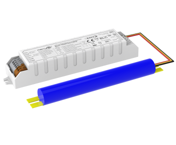
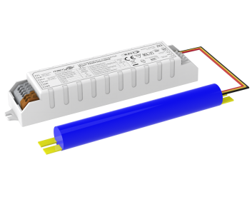
4W 3hours DALI Emergency pack with Autotest With 5 Years Warranty LifePO4 battery
| Place of Origin | China |
|---|---|
| Brand Name | Merrytek |
| Certification | CE, UKCA, UN38.3, MSDS |
| Model Number | KE004-04Dii180HE |
| Minimum Order Quantity | 100 |
| Price | Negotiation |
| Packaging Details | Packed in bubble bag firstly, and then reinforced with carton for outer packing |
| Delivery Time | 1, Sample and small order: Within 5 working days after receiving your payment. 2, Bulk order: 3-4 weeks after receiving deposit. |
| Payment Terms | T/T or Western Union |
| Supply Ability | 10,000pcs per month |
Product Details
| Rated Input Voltage | 220-240Vac 50Hz /60Hz | Emergency Power | 4W(Can Be Customized) |
|---|---|---|---|
| Emergency Time | 180min (Can Be Customized) | Warranty | 5 Years( Battery Is Included) |
| Load Output Voltage | 20-60Vdc | Working Temprature | 0℃~50℃ |
| IP Rating | IP20 | Battery Type | LifePO4 6.4V 3600mAh |
Product Description
4W 3hours DALI Emergency pack with Autotest With 5 Years Warranty LifePO4 battery
1. Description
- Constant power output LED emergency power supply with a wide output voltage range. With DALI interface and self-test function.
- DALI interface for controlled testing and monitoring.
- Input & output relay switching.
- LifePO4 battery with battery management.
- With multiple protection functions: battery overcharge, deep discharge protection, output short circuit protection.
2. Parameters
| Charge Part | KE004 | 04Dii180HE | |
| Rated input voltage | 220-240Vac 50Hz/60Hz | ||
| Rated input current | 0.06A Max. @230Vac | ||
| Input inrush current | <10A (Half current pulse width100μs) @230Vac | ||
| Power factor | ≥ 0.5@230Vac | ||
| Input power | < 4W@230Vac | ||
| Battery charging current | 350mA Max. | ||
| Battery charging time | 24 hours Max. | ||
| Emergency Part | Operating mode | Emergency mode | |
| Load type | LED | ||
| Emergency power | 4W | ||
| Emergency time | 3 hours or 1.5 hours (Set via jumper caps) | ||
| Load output current | 1200-67mA | ||
| Load output voltage | 20-60Vdc | ||
| Battery | LifePO4 (The battery capacity meets the emergency time at 25℃) | 6.4V 3.6Ah | |
| Battery warranty | Warranty 5 years @25℃. | ||
| Exception Driver Requirements | Surge current | 8A | |
| Input current | 3A Max. | ||
| Output current | 2A Max. | ||
| Emergency Function Test | Auto test | Self-test function. | |
| LED Indication | Fault/ test / Status | Reason | Charge Indicator Status |
| The battery is fully charged and operational | Standard daily use | ||
| solid green | |||
| LED Indication | Fault / test / Status | Reason | Charge Indicator Status |
| Emergency mode | Battery operation | ||
| Green and red off | |||
| Function test | Periodic self-test | ||
| Flashing Green 0.3 sec on 0.3 sec off | |||
| Duration test | Periodic self-test | ||
| Flashing Green 1 sec on 1 sec off | |||
| Charging fault | Incorrect charging current | ||
| Flashing Red 0.3 sec on 0.3 sec off | |||
| Battery failure / disconnected | The battery failed the duration test or function test | ||
| Flashing Red 1 sec on 1 sec off | |||
| LED fault | Not plugged in or damaged / faulty | ||
| solid red | |||
| Inhibit mode | Inhibit mode active | ||
| Double pulsing green | |||
| Abnormal protection | Battery over-charge/deep discharge protection | Yes | |
| Output over-voltage protection | Yes | ||
| Output overload protection | Yes | ||
| Output short circuit protection | Yes | ||
|
Operating Environment |
Operating temperature/humidity | 0℃…+50℃;Humidity:20%-75%(without condensation) | |
| Storage temperature/humidity | -5℃-35℃ | ||
| Case Max. Temp(Tc) | 75℃ | ||
|
Safety & EMC
|
Withstand voltage | 3000Vac 5mA 60s (Input “L N” – output “SEC+ SEC-) | |
| Safety standard | EN61347-1, 60598-2-22, 61347-2-7, 62034 | ||
| EMC standard | EN55015, EN61000-3-2, EN61000-3-3 | ||
| DALI protocol standard | IEC62386-101 / 102 / 202 DT1 | ||
| Battery standard | UN38.3 | ||
| Environmental protection requirements | Compliant with RoHS | ||
| Certification | CE | ||
| Others | (Terminal/wiring) specification | Press terminal, wire diameter: 0.5-0.75mm2 | |
| IP rating | IP20 | ||
| Type of protection | Class II | ||
| Installation type | Built-in installation | ||
| Dimension (driver) | 146*30*22.5mm | ||
| Packaging requirement | White box+Instruction manual+clapboard+outer carton(K=A) | ||
| Weight | 80g (driver) | ||
| Lifespan | 5 Year @Ta | ||
|
Notes: All parameters are tested on the input voltage 230Vac, the environment temperature 25℃, unless otherwise specified. |
|||
3. Dimension (Unit:mm)
LED Converter:

Battery:
Fig.1: Straight-line for IFR18650 Fig.2: Parallel for IFR18650
4. Wiring Diagram
Fig.A: With LED driver(Switched) and LED module for mains and emergency operation
Fig.B: With LED driver(Unswitched) and LED module for mains and emergency operation
Fig.C: With LED driver(Switched) and separated LED modules for mains and emergency operation
Fig.D: With the LED module for non-maintained emergency operation
5. Emergency Time Setting
6. Wire Preparation
- Solid or Stranded wire type:0.5 -0.75mm2
- To access or remove the wires from the terminals, use a screwdriver to push the buttons down
7. Automatic Test & Operation Instructions
- DALI bus has not been connected
1) Connect the wire according to the wiring diagram.
2) L,N power on, start the clock, and periodic self-test. These default times are factory pre-set, in accordance with the DALI standard EN 62386-202, to conduct an automatic function test every 7 days and a duration test every 52 weeks. Since the DELAY time is factory pre-set to Zero, all units are tested at the same time. Test times can be changed with a command over the DALI bus.
- DALI bus has been connected
1) DALI command from a suitable control unit can be used to initiate function and duration tests at individually selected times. Status flags are set for report back and data logging of results.
2) The DELAY and INTERVAL time values must be re-set when the emergency system test times are to be scheduled by a DALI control and monitoring system.
C. Clock
1) AC power is off, and the clock lasts for 7 days, Power on and re-time. Turn off the power supply, replace the battery. The clock will Re-time.
8. Battery Application Notice
1) The battery should be recharged and discharged semiannually in normal use conditions.
2) Do not connect to the circuit when the battery is not in use to prevent over-discharge of the battery due to self-consumption of the circuit board.
3) Please keep the battery away from the heat source when installing and using, and only allowed to be used in a certain working temperature range.
4) The battery should be stored in a dry place with a moderate, stable temperature.
5) After a long-time storage, the battery is cycled every 6 months as required.
Recommended Products